|
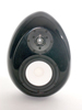
Walt's pictures are instructive on what the network really is on this box.
First, I assume the black goopy mass with two black leads is an iron core inductor, and my observations are based on that assumption.
From what I see, there are two networks in this box.
1. A RC network between the +/- terminals (either input or output terminals). This network may be a Zobel to flatten the impedance curve of the speaker or amplifier output for the second network to properly work.
2. A LCR network that is in series between the input and output. This is a resonant circuit, frequency set by the L and C in parallel, and damped by the parallel R which effectively sets the amplitude of the resonant peak by controlling the Q (damping factor). Based on the description in the white paper, the frequency is around 60Hz, the amplitude of the peak is between 8dB and 6dB based on the impedance seen by this circuit.
So my initial observation of this decreasing the level of the midrange/treble is incorrect. It only impacts the LF response.
I think such a resonant circuit inline with the speaker load probably is going to invalidate the validity of observations on the effect of damping factor at the amplifier end, in that the circuit plays around with unloading damping for it to work.
Also, the R in the LCR network is in parallel with the R in the inductor. Therefore the series resistance is the DC resistance of the inductor in parallel with this resistor, which will be much lower than the 10 ohms that Walt used to replace the network in his comparison, if I understand him correctly. I would expect something more like 1 ohm or so.
David
|
 Login
Login Register
 FAQ
FAQ Search