David McGown wrote:
Roscoe,
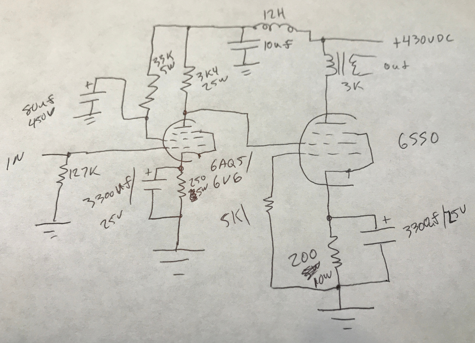
OK, here goes the Cliff Notes version... It's really a very simple amp, standard pentode operation of the driver, gain around 10 if I remember correctly. The output tube is just like a standard pentode output stage, except the control grid sees no signal. If you think about it, with no input signal at all, it operates exactly like any other self biased SE pentode operating stage. Plate at about 400VDC, screen grid at 250VDC, control grid at 0VDC, cathode at about 16VDC. The difference comes in where the signal is injected into the output stage... Take a look at a typical pentode characteristics curve:
The screen grid really does isolate the plate from the rest of the circuit. In a triode, if you increase plate voltage and keep everything else the same, plate current goes up. In a P/T, changing only the plate voltage does essentially nothing (unless you go to ridiculous extremes) but if you change screen grid voltage, you do get a significant change in current. That's what I'm doing here, modulating the screen voltage as a way to control output current. Doing things this way eliminates the huge power consumption/heat generation common on most DC tube designs, as the cathode can be at the same reference above ground it would be with typical control grid modulation. The 5.1K resistor probably isn't necessary, but I wasn't comfortable just connecting the grid to ground (why do I type gride every time and have to go back and remove the 'e'?) on the first try...
This design does make some significant demands on the driver though, keep in mind that you have to swing a lot of voltage AND supply current to the screen. You're not going to pull this off with a 12AX7 for a driver;)
I should have the parts to complete the stereo pair Monday, then I can give the design a fair test.
Roscoe