DCAudioDIY.com

DC Area Audio DIYer's Community
It is currently April 29th, 2024, 1:04 pm

All times are UTC - 5 hours [ DST ]


Post new topic Reply to topic  [ 9 posts ] 
Author Message
PostPosted: April 13th, 2024, 10:52 am 
Offline
User avatar

Joined: January 15th, 2015, 7:19 am
Posts: 1700
Location: Baltimore MD
I recently heard a PODCAST with Peter Qvortrup of Audio Note, and he said that said proper adjustment of an amplifier's time constant is important. Does anybody know what he is talking about?


Top
 Profile  
 
PostPosted: April 14th, 2024, 10:42 pm 
Offline

Joined: March 2nd, 2013, 2:43 pm
Posts: 219
Location: Potomac, MD
There are many time constants in an amplifier. To put it very simply, a time constant is like response time. This often refers to how a voltage decays in a resistor-capacitor combination after an impulse is applied or with a repetitive square wave. I say there are many of these in an amplifier, and here are some examples. A coupling capacitor followed by a resistor to ground has a time constant that describes a low-frequency limit for that particular part of the circuit. A circuit impedance with a parasitic or intentional capacitance to ground describes a high-frequency limit (time constant) for that particular part of the circuit. A decoupling network for power-supply filtering or stage isolation is usually a low-frequency limit, but can have high-frequency effects as well. A capacitor is called a reactive component in that it changes its impedance with frequency (AC). A resistor, on the other hand does not (ideal). Inductors are also reactive components, and inductor-resistor combinations have time constants as well. The impedance of inductors increases with frequency, where as with capacitors the impedance decreases as the frequency increases. A single time constant like one series capacitor followed by a resistor to ground exhibits a 6dB per octave roll off as a low-frequency limit. The exact curve looks like a bend in a flat-response line representing higher frequencies, and the 6-dB slope line at much lower frequencies than the defined time-constant-defined frequency. There is a region where these lines intersect that shows an actual curve with a gradual bend. By convention, the 3-dB down point represents the time constant which is expressed in seconds, or more commonly microseconds for audio. Without going into detail, circuits can have both a capacitor and an inductor to get a steeper cutoff slope. A common example is a crossover network in a speaker. Hope this helps.


Top
 Profile  
 
PostPosted: April 14th, 2024, 11:58 pm 
Offline

Joined: April 22nd, 2013, 12:58 pm
Posts: 286
Here's a common example that should be familiar to some folks. The RIAA phono equalization curve exists because bass notes needed to be toned down in order for a phono cartridge to be able to track the very large modulations in the groove, AND, the high frequencies needed to be boosted in order to minimize THD+noise as the phono cartridge tried to squeeze a decent signal out of smaller and smaller modulations. So, big bass cut and big treble boost. The actual equalization curve looks like this:

Image

The time constants are in seconds and the corresponding frequencies of the -3dB points are in Hertz (two pi radians per second).


Top
 Profile  
 
PostPosted: April 15th, 2024, 2:55 pm 
Offline

Joined: March 5th, 2013, 9:35 am
Posts: 261
Location: Highland, MD
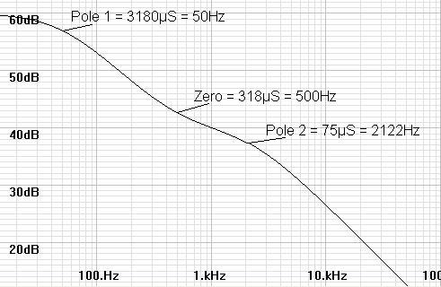
I think another thing to consider with time constants and filters is that a time constant represents when phase shifts occur. In FerdinandII's example he used the RIAA response: I don't have that circuit simulated but I have an inverse RIAA circuit used to test pre-amps.
Attachment:
Inverse RIAA Response.jpg
Inverse RIAA Response.jpg [ 164.84 KiB | Viewed 512 times ]

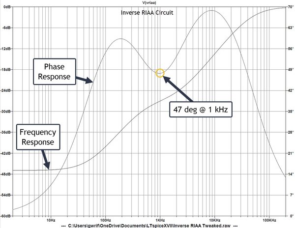
The one line shows the frequency response with respect to the left axis and the other line shows the associated signal-phase shift with respect to the right axis. Note that the output signal from this circuit is shifted by 47 deg at 1 kHz. This represents a time shift of about 130 usec and a sound-wave shift of 48 mm (ahead of the input signal, if I remember right.) Likewise, this output is shifted 10 deg at 10 Hz, 68 deg at 10 kHz, and 13 deg at 200 kHz.

(Please, someone correct me if this is wrong: I don't want to muddy the water!) :crazy:

The importance makes more sense to me in speakers. 1 kHz has a wavelength of 0.343 m in air at 20 deg C. The phase shift of 47 deg makes the sound wave appear 48 mm earlier than the speaker signal (almost 2 inches,) which will cause problems with sound stage and imaging in a two- or three-way speaker system.

I think that this is why time constants are important to keep track of. As dberning said, there are numerous RC, LC, RL, and LRC time constants in our circuits and if we can select the time constants to minimize phase shift, then we should have a system with better imaging and sound stage.

Or am I wrong? :confusion-confused:

_________________
- Guy


Top
 Profile  
 
PostPosted: April 15th, 2024, 4:26 pm 
Offline
User avatar

Joined: January 15th, 2015, 7:19 am
Posts: 1700
Location: Baltimore MD
In my amps, Glass bottle types there are very few caps in signal path other than the coupling caps.
I know if too high a value is selected you will loose bass response (help me if I am wrong).
What other effects would choosing wrong values will raise its ugly head


Top
 Profile  
 
PostPosted: April 15th, 2024, 5:32 pm 
Offline

Joined: July 17th, 2016, 6:24 am
Posts: 1108
Guy,

Your calculations do not seem correct. Pl. check.

Wavelength of audio signals in acoustic domain and their corresponding electrical signal are different.

Wavelength of acoustic signal = speed of sound / frequency

Wavelength of electrical signal = speed of light / frequency

Since the speaker drives are responding to electrical signals, we are only concerned with phase shifts in electrical domain.


Top
 Profile  
 
PostPosted: April 15th, 2024, 5:36 pm 
Offline

Joined: July 17th, 2016, 6:24 am
Posts: 1108
dberning wrote:
There are many time constants in an amplifier. To put it very simply, a time constant is like response time. This often refers to how a voltage decays in a resistor-capacitor combination after an impulse is applied or with a repetitive square wave. I say there are many of these in an amplifier, and here are some examples. A coupling capacitor followed by a resistor to ground has a time constant that describes a low-frequency limit for that particular part of the circuit. A circuit impedance with a parasitic or intentional capacitance to ground describes a high-frequency limit (time constant) for that particular part of the circuit. A decoupling network for power-supply filtering or stage isolation is usually a low-frequency limit, but can have high-frequency effects as well. A capacitor is called a reactive component in that it changes its impedance with frequency (AC). A resistor, on the other hand does not (ideal). Inductors are also reactive components, and inductor-resistor combinations have time constants as well. The impedance of inductors increases with frequency, where as with capacitors the impedance decreases as the frequency increases. A single time constant like one series capacitor followed by a resistor to ground exhibits a 6dB per octave roll off as a low-frequency limit. The exact curve looks like a bend in a flat-response line representing higher frequencies, and the 6-dB slope line at much lower frequencies than the defined time-constant-defined frequency. There is a region where these lines intersect that shows an actual curve with a gradual bend. By convention, the 3-dB down point represents the time constant which is expressed in seconds, or more commonly microseconds for audio. Without going into detail, circuits can have both a capacitor and an inductor to get a steeper cutoff slope. A common example is a crossover network in a speaker. Hope this helps.


David,

From Google. Is this correct?

Quote:
The time constant of an amplifier is the time period in which a signal is reduced to 1/e (i.e. about 37%) of the output signal.


Top
 Profile  
 
PostPosted: April 17th, 2024, 12:05 pm 
Offline

Joined: March 2nd, 2013, 2:43 pm
Posts: 219
Location: Potomac, MD
Quote:
The time constant of an amplifier is the time period in which a signal is reduced to 1/e (i.e. about 37%) of the output signal.


That is correct. I thought of mentioning that but I thought it might add confusion. The use of 1/e is a good way of dealing with time constants with impulse and square-wave characterization.


Top
 Profile  
 
PostPosted: April 18th, 2024, 9:45 am 
Offline

Joined: July 17th, 2016, 6:24 am
Posts: 1108
dberning wrote:
Quote:
The time constant of an amplifier is the time period in which a signal is reduced to 1/e (i.e. about 37%) of the output signal.


That is correct. I thought of mentioning that but I thought it might add confusion. The use of 1/e is a good way of dealing with time constants with impulse and square-wave characterization.


Thanks, David.


Top
 Profile  
 
Display posts from previous:  Sort by  
Post new topic Reply to topic  [ 9 posts ] 

All times are UTC - 5 hours [ DST ]


Who is online

Users browsing this forum: Bing [Bot] and 213 guests


You cannot post new topics in this forum
You cannot reply to topics in this forum
You cannot edit your posts in this forum
You cannot delete your posts in this forum
You cannot post attachments in this forum

Search for:
Jump to:  
Powered by phpBB® Forum Software © phpBB Group