New SE Amp deisgn...
November 19th, 2014, 2:21 pm
So, this one is only on paper at this point. Some of the values will probably have to change to reflect reality. I know I'm gonna have to replace the RC filter for the driver stage with an LC filter to keep the B+ for the driver stage high enough.
Unlike the PP amp, I'm not aware of any classic designs that this one looks a lot like
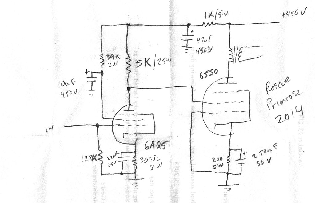
Hope to have a pair of these built before the end of the year...
Roscoe
Unlike the PP amp, I'm not aware of any classic designs that this one looks a lot like
Hope to have a pair of these built before the end of the year...
Roscoe
Re: New SE Amp deisgn...
November 19th, 2014, 2:43 pm
I have never been very successful using an audio tube in the screen-drive configuration in spite of a number of attempts. Not sure why, although a complicating factor is the high drive voltage required. The screen drive works well for tubes using low screen voltage such as TV sweep tubes. To be viable, screen drive should be around 800 volts p-p for most audio tubes, and 300 V p-p for TV sweep tubes. In both cases, a follower of some type is need to provide sufficient current.
David
David
Re: New SE Amp deisgn...
November 19th, 2014, 2:56 pm
I'd considered a follower (anode followers not withstanding ). In this case though, the driver is running at 45mA plate current, with a nominal 5mA on the screen grid of the 6550, so we'll have to see how it works out.... If it doesn't work, well, just one more bad experience to add to the learning....
Roscoe
Roscoe
Re: New SE Amp deisgn...
November 19th, 2014, 3:08 pm
Easy enough to retrofit a Mosfet as a source follower if it doesn't work well. Hard to imagine varying driver plate current by up to 20%, maybe more (+/-5mA out of idle of 45mA) not adversely affecting driver linearity.....but maybe a pentode won't care so much??? May want to make the driver screen supply a CCS.
As to the output tube, shouldn't be too difficult to switch to a horizontal output type if that doesn't work out, with a little pre-planning for that contingency.
But you knew that!
As to the output tube, shouldn't be too difficult to switch to a horizontal output type if that doesn't work out, with a little pre-planning for that contingency.
But you knew that!
Re: New SE Amp deisgn...
November 19th, 2014, 3:30 pm
Well, used as an SE output tube, the 6AQ5's plate current would vary much more than 10%, remember, the only way to get an output from a transformer secondary is to vary the current on the primary....
Roscoe
Roscoe
Re: New SE Amp deisgn...
November 19th, 2014, 4:53 pm
Roscoe Primrose wrote:Well, used as an SE output tube, the 6AQ5's plate current would vary much more than 10%, remember, the only way to get an output from a transformer secondary is to vary the current on the primary....
Roscoe
I do remember, and please correct me if I'm wrong (that's rhetorical, I know you will
I was convinced of the need for a very low source impedance when driving an output grid (or RIAA network, for that matter) when I heard David McGown's PowerDrive equipped amps. They were quite remarkable and without any discernible SS sonic artifacts. Whether it's avoiding blocking distortion, unloading the driver, or something else, IT WORKS!
Just a thought....
Slick
BTW, my SCA35 with 6HB6 outputs and PowerDrive is only missing a phono stage, cover and cosmetics. At the next meet, I'd like to have you give it a listen.
- Attachments
-
Re: New SE Amp deisgn...
November 19th, 2014, 6:04 pm
Stuart Polansky wrote:Roscoe Primrose wrote:Well, used as an SE output tube, the 6AQ5's plate current would vary much more than 10%, remember, the only way to get an output from a transformer secondary is to vary the current on the primary....
Roscoe
I do remember, and please correct me if I'm wrong (that's rhetorical, I know you will) but isn't the major source of distortion in an SE amp the output stage? If so, and if minimizing distortion (pleasant though some forms may be) is a goal in amp design (yes, not to the extent that other problems arise, such as TIM, or pinching with excessive global NFB), then wouldn't it make sense to try out a technique that most probably would reduce the distortion?
I was convinced of the need for a very low source impedance when driving an output grid (or RIAA network, for that matter) when I heard David McGown's PowerDrive equipped amps. They were quite remarkable and without any discernible SS sonic artifacts. Whether it's avoiding blocking distortion, unloading the driver, or something else, IT WORKS!
Just a thought....
Slick
BTW, my SCA35 with 6HB6 outputs and PowerDrive is only missing a phono stage, cover and cosmetics. At the next meet, I'd like to have you give it a listen.
I would like to hear that amp, I am restoring an SCA35 using Dave Gillespie's EFB circuit for the power supply...
Re: New SE Amp deisgn...
November 19th, 2014, 8:54 pm
I think I see Guy's CCS PC board in there.....