DCAudioDIY.com

DC Area Audio DIYer's Community
It is currently November 22nd, 2026, 9:11 am

All times are UTC - 5 hours [ DST ]


Post new topic Reply to topic  [ 48 posts ]  Go to page Previous  1, 2, 3, 4, 5
Author Message
PostPosted: November 15th, 2026, 9:00 pm 
Offline
User avatar

Joined: January 13th, 2016, 9:14 pm
Posts: 942
The prototypes of the converter with the TX2575 resistors and Staccato OSH-S opamps has begun.

Next is wiring the connections. Will be adding an extra ground pin for the trials with another discrete opamp.

The Sparkos Labs SS2590 discrete opamp is a studio style 990 opamp. High bias Class A output stage with large current output capability. It has on 2 onboard decoupling caps that will work when a pin that is not connected to the 8 pin adapter is grounded.


Attachments:
PXL_20261116_002952283.jpg
PXL_20261116_002952283.jpg [ 2.36 MiB | Viewed 9391 times ]
Top
 Profile  
 
PostPosted: November 16th, 2026, 1:15 am 
Offline
User avatar

Joined: July 24th, 2015, 4:17 pm
Posts: 1908
Location: Parkville, Maryland
HAL wrote:
Thanks for the recommendation.

Found the RX70 spec sheet for the resistors. Sounds like the are bifalar wound to cancel inductance. Nice that they are 0.01% tolerance. They would work well in crossovers like the Mills resistors.

Their TC is 10ppm. Very good by metal film resistor specs usually around 25ppm for very good ones. That is 10x the TX2575 TC spec at 1ppm. That is what matters in feedback loops.

Since the TX2575 element is about 1/8in x 1/8in, their self inductance will the very low to start. The Vishay S102K Bulk metal foils were bigger.

Will look into them for a listening trial.

BTW -- the Vishays and the bobbins have one particular feature in common. The lead-outs are welded to the resistive element. Metal and carbon film resistors' resistive elements are terminated with friction-fit end caps. The lead-outs are only welded to the end-caps.

Think about it.

_________________
Walt


Top
 Profile  
 
PostPosted: November 16th, 2026, 3:30 am 
Offline

Joined: April 22nd, 2013, 12:58 pm
Posts: 312
SoundMods wrote:
BTW -- the Vishays and the bobbins have one particular feature in common. The lead-outs are welded to the resistive element. Metal and carbon film resistors' resistive elements are terminated with friction-fit end caps. The lead-outs are only welded to the end-caps.

Think about it.


I hear a diode forming..... LOL


Top
 Profile  
 
PostPosted: November 16th, 2026, 7:10 am 
Offline
User avatar

Joined: January 13th, 2016, 9:14 pm
Posts: 942
SoundMods wrote:
HAL wrote:
Thanks for the recommendation.

Found the RX70 spec sheet for the resistors. Sounds like the are bifalar wound to cancel inductance. Nice that they are 0.01% tolerance. They would work well in crossovers like the Mills resistors.

Their TC is 10ppm. Very good by metal film resistor specs usually around 25ppm for very good ones. That is 10x the TX2575 TC spec at 1ppm. That is what matters in feedback loops.

Since the TX2575 element is about 1/8in x 1/8in, their self inductance will the very low to start. The Vishay S102K Bulk metal foils were bigger.

Will look into them for a listening trial.

BTW -- the Vishays and the bobbins have one particular feature in common. The lead-outs are welded to the resistive element. Metal and carbon film resistors' resistive elements are terminated with friction-fit end caps. The lead-outs are only welded to the end-caps.

Think about it.


The TX2575 are exactly the same termination as the Vishay's. Welded to the element. Just no epoxy housing like the S102K. They also make a surface mount version of the resistor without the leads.


Top
 Profile  
 
PostPosted: November 16th, 2026, 1:32 pm 
Offline
User avatar

Joined: July 24th, 2015, 4:17 pm
Posts: 1908
Location: Parkville, Maryland
HAL wrote:
The TX2575 are exactly the same termination as the Vishay's. Welded to the element. Just no epoxy housing like the S102K. They also make a surface mount version of the resistor without the leads.

FYI -- The plastic package as part of the Vishay construction does not come in contact with the resistive element. The ceramic body of the resistor with the laser-etched non-inductive element is contained in a silicon "sock" and that assembly is inside the plastic pack. Also -- another fun fact -- the welded connections to the resistive element are at the top of the package and routed down to where the leads exit. Why? NASA had issues with failures due to extreme forces created by the massive vibration energy requirements of getting heavy loads into orbit and back again. Although bare naked bulk-film resistors have a "cult" following, the end result in sound quality is more myth than any realized gain in sound quality. The Vishay packaging also helps isolate the resistive element from piezoelectric effects due to acoustic breakthrough. So --what's good for the space effort is really good for audio playback. One final thought -- the surface mount version is not the same thing. The SMD resistors have friction-fit end-caps for soldering and not welded leads.

https://vpgfoilresistors.com/products/t ... -resistors


Attachments:
28877-pt-large.jpg
28877-pt-large.jpg [ 23.69 KiB | Viewed 8775 times ]

_________________
Walt
Top
 Profile  
 
PostPosted: November 17th, 2026, 8:54 am 
Offline
User avatar

Joined: January 13th, 2016, 9:14 pm
Posts: 942
"Texas Components Bulk Metal Foil resistors (utilizing technology developed with Vishay Precision Group) are constructed around a high-precision, photo-etched metal alloy layer bonded to a ceramic substrate.

Core Construction Elements

• Resistive Foil Element: A special nickel-chromium (Ni/Cr) alloy foil is cemented or bonded directly onto a flat, thermally conductive ceramic (such as alumina) substrate.
• Photo-Etched Planar Pattern: An ultra-fine photo-etching technique defines a serpentine or custom geometric resistive pattern out of the flat foil. Adjacent conductors are laid out in opposing or interlaced directions to dramatically cancel out inductance and capacitance (achieving a non-inductive, non-capacitive design).
• Trimming & Calibration: Values are finely adjusted using shorting bar trimming or selective cutting/modifying of the etched foil paths to reach ultra-tight tolerances (down to ±0.001%).
• Solder-Free / Welded Terminations: In high-reliability and specialized versions (such as the TXZ series), leads connect to the foil element at the top of the package using solder-free, all-welded construction to eliminate latent failures from solder reflow or thermal stress.
• Post-Manufacturing Operations (PMO): Finished units undergo specialized stabilization cycles—including thermal shock, power conditioning (power shots), and burn-in—to lock in long-term drift resistance and mechanical stability."


Top
 Profile  
 
PostPosted: November 17th, 2026, 3:25 pm 
Offline
User avatar

Joined: July 24th, 2015, 4:17 pm
Posts: 1908
Location: Parkville, Maryland
HAL wrote:
"Texas Components Bulk Metal Foil resistors (utilizing technology developed with Vishay Precision Group) are constructed around a high-precision, photo-etched metal alloy layer bonded to a ceramic substrate.

Core Construction Elements

• Resistive Foil Element: A special nickel-chromium (Ni/Cr) alloy foil is cemented or bonded directly onto a flat, thermally conductive ceramic (such as alumina) substrate.
• Photo-Etched Planar Pattern: An ultra-fine photo-etching technique defines a serpentine or custom geometric resistive pattern out of the flat foil. Adjacent conductors are laid out in opposing or interlaced directions to dramatically cancel out inductance and capacitance (achieving a non-inductive, non-capacitive design).
• Trimming & Calibration: Values are finely adjusted using shorting bar trimming or selective cutting/modifying of the etched foil paths to reach ultra-tight tolerances (down to ±0.001%).
• Solder-Free / Welded Terminations: In high-reliability and specialized versions (such as the TXZ series), leads connect to the foil element at the top of the package using solder-free, all-welded construction to eliminate latent failures from solder reflow or thermal stress.
• Post-Manufacturing Operations (PMO): Finished units undergo specialized stabilization cycles—including thermal shock, power conditioning (power shots), and burn-in—to lock in long-term drift resistance and mechanical stability."

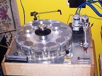
You seem to be enamored over all of these specs and I don't disagree about the sound quality -- there has been enough said about the bulk-film product. All I am saying is that the bobbins serve the music in ways I had not expected when doing trials. They're musical in all the good ways. They don't smother -- they don't sweeten -- they don't add any electronic signature -- they don't add "detail" that's not there. They simply step out of the way.

If you want specs try Vishay-Angstrom glass-hermetic metal-film resistors filled with Helium @ $80 a pop in small qualities. For our audio purposes they're a waste of money. I got an engineer's selection from the Boeing warehouse in Everett, Washington on the cheap and found that they ad an electronic edge to the music. And yet -- in the reciprocal position of a feedback loop they have their uses. Go figure.

Attachments:
s-l400.jpg
s-l400.jpg [ 7.17 KiB | Viewed 7530 times ]

_________________
Walt
Top
 Profile  
 
PostPosted: November 17th, 2026, 3:48 pm 
Offline
User avatar

Joined: January 13th, 2016, 9:14 pm
Posts: 942
And the fundamental spec of TC for the Vishay-Angstrom glass-hermetic metal-film resistors is 15-25x higher than the TX2575 at TC=1ppm. The TX is more stable thermally with signal and 4.7x cheaper.

The TX sound excellent and add nothing to what I hear. They are in the circuit now, so I do not need to experiment further with resistors.


Top
 Profile  
 
Display posts from previous:  Sort by  
Post new topic Reply to topic  [ 48 posts ]  Go to page Previous  1, 2, 3, 4, 5

All times are UTC - 5 hours [ DST ]


Who is online

Users browsing this forum: No registered users and 5 guests


You cannot post new topics in this forum
You cannot reply to topics in this forum
You cannot edit your posts in this forum
You cannot delete your posts in this forum
You cannot post attachments in this forum

Search for:
Jump to:  
Powered by phpBB® Forum Software © phpBB Group